Advertisement [ ? ]
Site Links
- Lease Calculator
- Advertise
- My Car ongoing Review
- Members' Chat
- Cars For Sale
- Car Dealers
- Honda "Fit" Manual
- Hyperflex Bushings
- For Sale
- Fix your Car
- Car Manuals
- other manuals - Reference Materials
- DIY Repairs
- Articles
- Video
- Link with Us
- Search Help
- Code your Mac!
- Fly, race, anything R/C
Chrysler Dodge Plymouth Minivan Bendix 10 Antilock Brakes
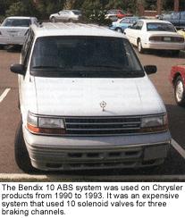
The Bendix 10 ABS system was introduced in 1990 on the Chrysler New Yorker, Imperial, Fifth Avenue and Dodge Dynasty, also the 1991 Dodge Caravan and Plymouth Voyager minivans, and the Eagle Premier. It was used only three years and was discontinued after the 1993 model year.
Bendix 10 is similar to the Bendix 9 ABS system used on Jeeps from this vintage. It uses an integral master cylinder/hydraulic modulator assembly with a remote pump and motor for power assist braking and anti-lock braking. It is an expensive unit (OEM list price $1,510!).
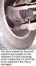
The system has four wheel speed sensors (all of which are nonadjustable). The tone wheels for the front sensors are located on the outboard CV-joint housings, which means the CV joint has to be replaced if the ring is damaged.
The Bendix 10 system divides the brakes into three-channels for anti-lock braking. The front brakes are controlled independently while the rear brakes are controlled as a pair.
It is called Bendix "10" because the hydraulic modulator contains 10 solenoid valves. There are four isolation solenoid valves (one for each wheel), and three decay and 3 build valves for each of the front brakes and both rear brakes. The extra isolation solenoid in this system helps reduce pedal pulsation and feedback during anti-lock braking.
When wheel lockup is about to occur, the controller energizes the isolation solenoid to block off the brake circuit to the affected wheel. It then energizes the decay solenoid so pressure can be released from the wheel, and reapplies brake pressure by deenergizing the decay solenoid and energizing the build solenoid. Pressure is provided by the accumulator and remote pump motor. The system cycles 15 to 20 times a second during ABS braking with no loss of pedal height.
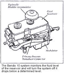
Bendix 10 has two accumulators. The large high-pressure accumulator located on the master cylinder booster assembly is precharged with nitrogen to 1,000 psi, and has a normal operating pressure range of 1,600 to 2,000 psi. The accumulator is a serviceable item, but it must be depressurized prior to removal by applying the brakes 40 times with the key off.
A second low pressure accumulator that is precharged to 460 psi and uses a sliding piston rather than a diaphragm is located on the pump/motor assembly. It is not serviceable. There is a fluid filter in the pump high-pressure line that can be serviced.
Other components on the modulator include a dual function pressure switch located on the bottom of the modulator. This switch turns the remote pump motor on and off by grounding the pump motor relay through the starter solenoid. The switch maintains accumulator pressure by turning the pump on when pressure drops below 1,600 psi, and off when pressure reaches 1,800 to 2,000 psi. This switch also warns the ABS controller if accumulator pressure drops below 1,000 psi. When the switch opens, the red Brake and yellow ABS warning lights are illuminated, and the ABS system is disabled. A fault message is set if the problem does not go away within two minutes.
There is also a differential pressure switch to detect pressures differences of more than 300 psi between the primary and secondary sides of the brake hydraulics. A problem here will illuminate both warning lights.
Two pressure sensors are also used in the Bendix 10 system on the modulator assembly to detect pressure problems. Each generates a voltage of 0.15 to 5 volts that is proportional to the amount of pressure. One monitors boost pressure and is located on the bottom of the modulator assembly. The other monitors primary pressure (which Chrysler refers to as the "delta" pressure) in the master cylinder and is located on the left side of the hydraulic assembly.
A fluid level switch on the reservoir keeps an eye on the fluid level. The switch consists of a float and magnetic reed switch which closes when the fluid level is too low. This will illuminate both warning lights and disable the ABS system.
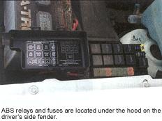
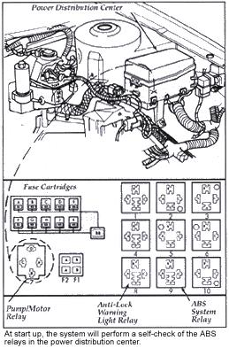
The ABS controller in vehicles with the Bendix 10 system is usually found under the battery tray. Power to the controller is provided through a relay in the power distribution center located on the left side of the engine compartment near the engine computer.
BENDIX 10 ANTILOCK BRAKES FAULT DIAGNOSTICS
The ABS controller conducts a self-test when the vehicle is started. This checks electrical connections and relays. The ABS warning light comes on about 1 or 2 seconds before going out. When vehicle speed reaches three miles per hour, the controller cycles the modulator solenoid valves. This test will not occur if the driver has the brake pedal depressed.
Chrysler service literature refers to two types of faults: latching and non-latching. Latching faults are ones that are serious enough to prevent the ABS system from functioning properly. When a latching fault is detected, the ABS system is disabled and will remain disabled until the ignition switch is reset. The ABS warning light will also remain on. A non-latching fault will illuminate one or both warning lights as long as the fault exists, but the light will go out once the fault no longer exists. In most cases, a fault message will be logged.
If the ABS light does not illuminate when the ignition is on because of a burned out bulb, the system is designed so the red BRAKE light will illuminate if there is a system fault.
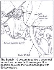
Accessing the ABS diagnostics requires a scan tool (Chrysler DRB II, DRB III or aftermarket equivalent). There are no manual flash codes. In fact, there are no codes at all. The Bendix 10 system displays "fault messages" rather than two or three-digit numeric codes.
Faults are stored in a nonvolatile memory which means they cannot be erased by pulling the ABS fuse. The only way they can be erased is with a scan tool, or by cycling the ignition switch 50 times (with no fault present).
The diagnostic connector on Bendix 10 applications is located under the dash, left of the steering column. It is a 6-way blue connector.
BENDIX 10 ANTILOCK BRAKES TROUBLESHOOTING
Keep in mind that brake system service on Chrysler products equipped with Bendix 10 ABS is the same as those that do not have ABS, except for the master cylinder. Most brake problems are not ABS-related, so do not blame the ABS system if the brakes are noisy, pulling, dragging or soft. Remember, the only time ABS affects braking is during hard stops or when braking on wet, slick or slippery surfaces. Of course, Bendix 10 also provides power assist braking, so pedal effort can be affected if the pump or accumulator fail.
There are several service precautions you should keep in mind when working on this type of ABS system.
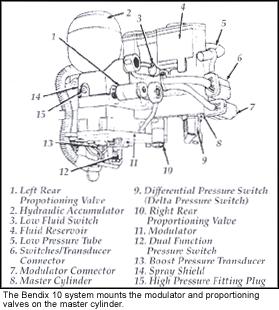
- Never do any brake work or open any hydraulic lines without first depressurizing the high pressure accumulator. Pump the brake pedal firmly 40 times while the ignition is off.
- Never connect or disconnect any electrical part of the ABS with the key on. This is especially applicable to the controller.
- Do NOT use electrical arc welding equipment on the vehicle without electrically disconnecting the controller.
- After replacing any major ABS component, verify system operation with a scan tool and/or test drive.
- Do NOT use a fast charger on the battery. If the battery needs to be fast charged, disconnect the battery from the electrical system. Never disconnect the battery while the engine is running.
- If you are replacing friction material, rotors, drums, any part of the master cylinder booster assembly, any hydraulic component or hardware, use high quality replacement parts that meet OEM specifications.
Prior to checking the system for fault messages, give the vehicle a preliminary visual inspection to check for obvious problems:
- Confirm whether or not one or both warning lights are still on by doing a bulb check and then starting the engine. If the yellow and/or red lights remain on, the system has a fault that will require further diagnosis.
- If both warning lights fail to illuminate when the key is turned on, check all system fuses including the ones for the instrument cluster. Also check the two warning light relays in the engine compartment.
- Check the BRAKE warning light by turning the key on and applying the parking brake. The light should come on. It should then go out when you release the brake.
- Check the electrical connections on the motor and pump assembly, and the master cylinder/modulator assembly.
- Be sure the brake fluid is at the proper level. If low or if the red BRAKE light is on, check the entire system for leaks.
If you discovered no obvious problems during your preliminary inspection, go ahead and use your scan tool to check for fault messages and to perform various system tests.
WARNING LIGHTS
Some Bendix 10 faults will illuminate the ABS warning light, some will illuminate only the BRAKE warning light, and some will illuminate both lights.
A problem with the ABS relay, ABS controller, hydraulic modulator assembly, any of the ABS solenoids or wheel-speed sensors will illuminate the ABS warning light when the problem is detected. The ABS warning light will remain on.
A boost pressure problem or low accumulator pressure will turn on both the ABS and BRAKE warning lights, but only when the brakes are applied.
A low fluid level or a parking brake that is engaged will cause the BRAKE warning light to come on immediately and remain on. The ABS warning light will come on when the vehicle speed exceeds 3 mph.
A problem with the primary or delta pressure sensor will cause the BRAKE warning light only to come on.
Wheel-Speed Sensor Checks
If you have a wheel speed sensor fault message, check the continuity of the wheel-speed sensor circuit and measure the resistance of the sensor. Front and rear wheel-speed sensors should read 1,000 to 4,000 ohms.
If the sensor and wiring are OK, inspect the wheel-speed sensor for metallic debris sticking to the magnetic tip, and check the sensor tone ring for chipped, cracked or missing teeth.
PRESSURE & VOLTAGE CHECKS
If you find a boost pressure or low accumulator fault message, use a scan tool or DVOM to check the boost pressure sensor voltage. It should be four volts or less depending on the amount of pressure in the accumulator. Push the brake pedal down and hold. If the boost pressure sensor reading is 1.95 volts or less, system pressure is low and needs to be checked. The primary pressure sensor should read 0.15 to 0.45 volts with the brakes released and ignition on.
The operation of the pump and accumulator can be checked by completely depressurizing the system (pump brake pedal 40 times with key off), then connecting a high pressure brake gauge to the high pressure fitting on the side of the hydraulic modulator just below the accumulator (there is a removable plug).
When the ignition is turned on, pressure should build quickly (at least 400 psi within two minutes). The pressure reading with a good pump should rise quickly to about 460 psi, then rise at a slower rate to about 1,000 psi, then increase very slowly until it reaches a maximum pressure of about 1,800 psi and shuts off. The pump should restart when accumulator pressure drops below about 1,600 psi.
If the pump motor stops running before it reaches 1,800 psi, or if the pumps fails to shut off, replace the dual function pressure switch on the bottom of the hydraulic modulator. Chrysler's special tool for doing this is P/N 6607.
If the pressure rises normally, turn the ignition off when it reads at least 1,200 psi and watch the gauge. Pressure should hold steady if the accumulator and modulator are good and the system has no leaks. If pressure drops more than 50 psi within a minute, the accumulator is not holding pressure or the modulator is leaking pressure internally.
The boost pressure switch can also be checked as system pressure comes up. At 1,000 psi, the switch should read 2.03 to 2.33 volts. If the boost pressure sensor needs to be replaced, Chrysler has another special tool (P/N 6684) for this job.
FILLING & BLEEDING
When filling the system with brake fluid, a special procedure is needed to assure a complete fill. Air inside the system may set a primary pressure/delta pressure fault message.
- Fill the reservoir to the full mark.
- Start the engine and pump the brakes until the booster pump/motor assembly turns on.
- Stop pumping the brakes and wait for the pump to shut off.
- Recheck the fluid level and add as needed.
Before bleeding the brake lines (manual, pressure or vacuum), depressurize the accumulator (pump pedal 40 times with key off). Then proceed as usual using the following sequence: left rear, right rear, left front and right front.
Antilock Brake Systems
ABS System Application Chart (by vehicle year, make & model)
Antilock Braking Systems (1998 model year)
ABS Systems Come Under Fire
New ABS Diagnostic Testers
Pulling ABS Diagnostic Codes
Honda Antilock Brakes
GM Delphi DBC-7 ABS Antilock Brakes
Jeep Bendix 9 Antilock Brakes
Kelsey-Hayes RWAL Rear Wheel Antilock Brakes
Kelsey-Hayes 4WAL Antilock Brakes
Teves Mark 20 Antilock Brakes
Bleeding ABS Brake Systems
Electronic Stability Control
Brake-By-Wire
Antilock Brake Guide product information
GM SUV Recall for ABS problem (August 2005)
Fixes For Common Brake Problems
